

-
Welcome to Tacoma World!
You are currently viewing as a guest! To get full-access, you need to register for a FREE account.
As a registered member, you’ll be able to:- Participate in all Tacoma discussion topics
- Communicate privately with other Tacoma owners from around the world
- Post your own photos in our Members Gallery
- Access all special features of the site
 Heat vent slection
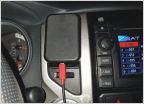
 Drone Mobile by Compustar
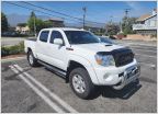 Looking to join the family! Opinions needed on a truck I am looking to buy!
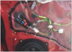 My Radio upgrade saga
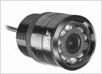 Aux backup light and under mount backup cameras?
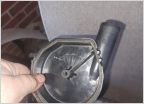 Internal filter/ pump
Replacement of Radiator, Thermostat, Water Pump, VVTi Filters, (but not) Valve Cover Gasket
Discussion in '2nd Gen. Tacomas (2005-2015)' started by eherlihy, Dec 27, 2024.
Products Discussed in


