

-
Welcome to Tacoma World!
You are currently viewing as a guest! To get full-access, you need to register for a FREE account.
As a registered member, you’ll be able to:- Participate in all Tacoma discussion topics
- Communicate privately with other Tacoma owners from around the world
- Post your own photos in our Members Gallery
- Access all special features of the site
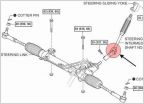 2nd gen lower steering shaft rebuild DIY :)
 Front / Rear Diff oil change
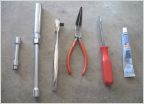 How To - Change Spark Plug 1st Gen 95.5-04 2RZ-FE(2.4L)/3RZ-FE(2.7L)
 Back Up Sensor Install How To
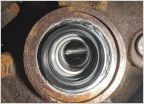 CV Axle Seal Install Issue - Thoughts?
09 Always-On Rear View Camera Wiring diagram (check my work)
Discussion in 'Technical Chat' started by Crom, Aug 10, 2011.
Page 1 of 2
Page 1 of 2


