

-
Welcome to Tacoma World!
You are currently viewing as a guest! To get full-access, you need to register for a FREE account.
As a registered member, you’ll be able to:- Participate in all Tacoma discussion topics
- Communicate privately with other Tacoma owners from around the world
- Post your own photos in our Members Gallery
- Access all special features of the site
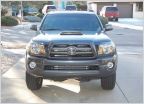 SONY headunit for sale
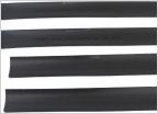 FS: Tacoma Double Cab Door Sill Protectors
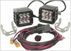 FS: Brand New Rigid Dually D2 LEDs
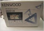 Kenwood DNX5120 DVD, Nav, Sat radio.
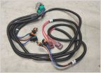 Sandman614 NC Garage Sale
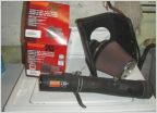 K&N filter and K&N intake.
Waterproof Fuse and Relay Boxes - RFRM (10 relay) & RTMR (5 Relay) no Blue Sea/ SPOD
Discussion in 'Buy / Sell / Trade' started by skygear, Jul 15, 2014.
- Thread Status:
- Not open for further replies.
Page 101 of 109
Page 101 of 109
- Thread Status:
- Not open for further replies.
Products Discussed in


