-
Welcome to Tacoma World!
You are currently viewing as a guest! To get full-access, you need to register for a FREE account.
As a registered member, you’ll be able to:- Participate in all Tacoma discussion topics
- Communicate privately with other Tacoma owners from around the world
- Post your own photos in our Members Gallery
- Access all special features of the site
 Wiring LEDs in Front Light Bar, Rock Lights, Puddle Lights, Rear, Footwell, Bed, Map and Dome
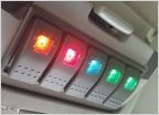 Switch panel using the overhead sunglass holder
 Nfab Light bar w/ (2) Hella 700 and (2) Hella 500?
 Any input on these
 8 gang switch panel
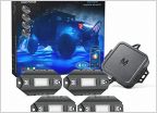 MICTUNING Rock Light Experiences?
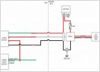
Wiring Schematic for Off Road Led light w/ Push Switch and 5 pin Relay
Discussion in 'Lighting' started by ekoziko, Oct 21, 2016.