-
Welcome to Tacoma World!
You are currently viewing as a guest! To get full-access, you need to register for a FREE account.
As a registered member, you’ll be able to:- Participate in all Tacoma discussion topics
- Communicate privately with other Tacoma owners from around the world
- Post your own photos in our Members Gallery
- Access all special features of the site
 Tretiak30's LT Taco w/37s
 Kappes03's Storm Trooper..ish Build (SOLD) :(
 Turner's Updated 2011 Build
 Mademan925's Truck....
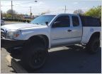 Buyobuyo's Build Thread
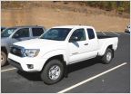 Scott B.'s 2015 AC Build - Expo Style
ramonortiz55's scandalous build - if it doesn't feel right, you're doing it right
Discussion in '2nd Gen. Builds (2005-2015)' started by ramonortiz55, Aug 19, 2015.
Page 7 of 8
Page 7 of 8