

-
Welcome to Tacoma World!
You are currently viewing as a guest! To get full-access, you need to register for a FREE account.
As a registered member, you’ll be able to:- Participate in all Tacoma discussion topics
- Communicate privately with other Tacoma owners from around the world
- Post your own photos in our Members Gallery
- Access all special features of the site
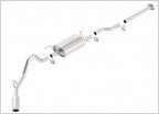 Second Gen Exhaust
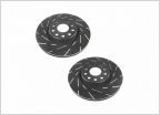 After market brakes
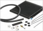 Supercharger check list.
 Made a mistake...
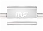 Magnaflow 18" on 2.7L? Help Me
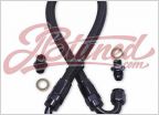 URD Fuel Pump Upgrade fittings
2TR-FE AEM F/IC-6 Installation Guide
Discussion in 'Performance and Tuning' started by dirtdigginjoe, Nov 14, 2017.


