-
Welcome to Tacoma World!
You are currently viewing as a guest! To get full-access, you need to register for a FREE account.
As a registered member, you’ll be able to:- Participate in all Tacoma discussion topics
- Communicate privately with other Tacoma owners from around the world
- Post your own photos in our Members Gallery
- Access all special features of the site
 Has anyone cut open a YZZG2?
 Febest tensioner pulley
 Inner steering bellows clamps
 Outlet Wiring
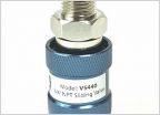 Arb twin air compressor question or air system related question.
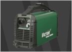 Plasma cutter, bang for the buck?
Ken the electrical guy Q n A
Discussion in 'Technical Chat' started by Kens04Taco, Oct 8, 2019.
Page 8 of 36
Page 8 of 36