

-
Welcome to Tacoma World!
You are currently viewing as a guest! To get full-access, you need to register for a FREE account.
As a registered member, you’ll be able to:- Participate in all Tacoma discussion topics
- Communicate privately with other Tacoma owners from around the world
- Post your own photos in our Members Gallery
- Access all special features of the site
 I'm losing my mind trying to find these mounts.
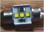 Festoon 31mm to 400lm conversion - no BS
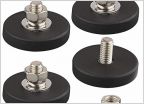 Matt Gecko's under hood LED lighting ket - hood switch install
 Headlight Recommendations
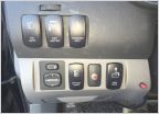 Fog Light Switch
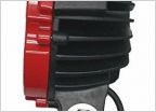
 Auxbeam 32” Straight and 42” Curved 5D Series Cree Combo Light Bar Installation And Review
DIY easy $10 trailer lights plugin fix
Discussion in 'Lighting' started by keakar, Oct 12, 2014.


