

-
Welcome to Tacoma World!
You are currently viewing as a guest! To get full-access, you need to register for a FREE account.
As a registered member, you’ll be able to:- Participate in all Tacoma discussion topics
- Communicate privately with other Tacoma owners from around the world
- Post your own photos in our Members Gallery
- Access all special features of the site
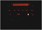 HVAC LEDs out!?
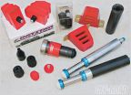 Options to increase payload
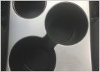 Center console mask
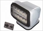 What are my options for spotlights?
12Pin DRL Flasher Relay LED Modification (Another One)
Discussion in '2nd Gen. Tacomas (2005-2015)' started by jad3d, Aug 19, 2016.

