

-
Welcome to Tacoma World!
You are currently viewing as a guest! To get full-access, you need to register for a FREE account.
As a registered member, you’ll be able to:- Participate in all Tacoma discussion topics
- Communicate privately with other Tacoma owners from around the world
- Post your own photos in our Members Gallery
- Access all special features of the site
 Loose weatherstripping on driver/passenger door
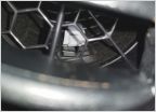 Air freshener piece fell into AC vent
 2017 Tacoma 3rd Gen Sport V6 3.5 OBD not Reading - Manual Transmission
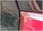 Chipped paint on tailgate. Leave it? Touch it up?
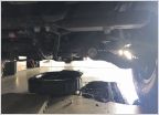 First time doing my oil changed on my Tacoma....
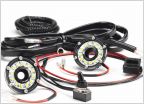 Looking for hood light
4-pin trailer to third brake light for Softopper
Discussion in '3rd Gen. Tacomas (2016-2023)' started by drewby, Feb 22, 2022.
Page 1 of 2
Page 1 of 2
Products Discussed in


