

-
Welcome to Tacoma World!
You are currently viewing as a guest! To get full-access, you need to register for a FREE account.
As a registered member, you’ll be able to:- Participate in all Tacoma discussion topics
- Communicate privately with other Tacoma owners from around the world
- Post your own photos in our Members Gallery
- Access all special features of the site
 Audio Help
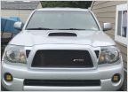 Tips on replacement headlights and fog lights
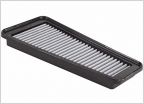 AFE Filter Leak
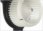 How do I fix a chirping fan in cab?
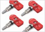 TPMS sensors
Add a key fob to your factory fob-less truck, under $20, no dealer visit
Discussion in '2nd Gen. Tacomas (2005-2015)' started by 241240, Apr 28, 2019.

