1. Welcome to Tacoma World!

    You are currently viewing as a guest! To get full-access, you need to register for a FREE account.

    As a registered member, you’ll be able to:
    • Participate in all Tacoma discussion topics
    • Communicate privately with other Tacoma owners from around the world
    • Post your own photos in our Members Gallery
    • Access all special features of the site
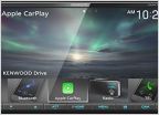
Assembled a fuse box and some switches

Discussion in 'Audio & Video' started by orangeglo, Oct 28, 2015.

  1. Oct 28, 2015 at 7:55 PM
    #1
    orangeglo

    orangeglo [OP] ¯\_(ツ)_/¯

    Joined:
    Jul 31, 2014
    Member:
    #135144
    Messages:
    177
    Gender:
    Male
    Los Angeles, CA
    Vehicle:
    2011 DCSB OR
    Finally finished wiring up a bussman 10 relay box and 12 switches.

    I used a Iggy switch panel for the cubby in front of the shifter (auto).
    http://iggycorp.com/accessories.php

    I cut my sunglasses holder to fit another 6 switches.

    All switches are from OTTRATW.
    https://www.otrattw.net/

    Box is a Bussmann 15401-2-0-1-0A RFRM.
    http://www.waytekwire.com/item/46354/Bussmann-15401-2-0-1-0A-RFRM-Panel-/

    Mounting plate for bussman box from yotamac.
    https://www.tacomaworld.com/threads...-blue-sea-systems-and-mounting-plates.294195/

    Almost all of the connectors are Metri Pack 280. Although I did end up using a weather pack 6 pin for the sunglasses holder switch panel. Could have just used two metri 280 three pin connector, but I got it stuck in my head I wanted a 6 pin connector for some reason. Connectors were sources from waytek.
    http://www.waytekwire.com/products/

    Most of the wire came from wirebarn. I used 12g and 18g GXL.
    http://www.wirebarn.com/

    Going to install tomorrow. Hope I don't light my truck on fire!

    [​IMG]
    [​IMG]
    [​IMG]
    [​IMG]
    [​IMG]
    [​IMG]
    [​IMG]
     
    Last edited: Oct 28, 2015
  2. Oct 28, 2015 at 8:06 PM
    #2
    InTheRough

    InTheRough Well-Known Member

    Joined:
    Jan 29, 2013
    Member:
    #96438
    Messages:
    3,001
    Gender:
    Male
    First Name:
    Kolt
    Gig Harbor, WA
    Vehicle:
    '20 Tundra Platinum
    Rock Warrior wheels
    That's the box that I would like to get but I have no idea how to wire it neatly.

    Good job on the install.
     
  3. Oct 28, 2015 at 8:12 PM
    #3
    orangeglo

    orangeglo [OP] ¯\_(ツ)_/¯

    Joined:
    Jul 31, 2014
    Member:
    #135144
    Messages:
    177
    Gender:
    Male
    Los Angeles, CA
    Vehicle:
    2011 DCSB OR
    If you wire the entire thing at once like I did, it is really hard to keep the whole thing neat. There are just so many wires. There are 40 wires coming off the box. The 20 that bridge the power and ground look pretty neat before the rest go in.

    I don't have anything planned for 7 of those always hot red/black pairs, so I probably didn't have to wire them all in, but I didn't want to have to come back to it later. Without those it looks much neater.
     
  4. Oct 28, 2015 at 8:48 PM
    #4
    tacomgee

    tacomgee just ain't care....

    Joined:
    Aug 5, 2014
    Member:
    #135522
    Messages:
    4,830
    Gender:
    Male
    First Name:
    Blake
    NorCal - Santa Rosa
    Vehicle:
    2015 Supercharged Taco
    Mostly whatever sweet stuff I can find at Vatozone
    I really wish i knew more about wiring. Looks really clean!
     
  5. Oct 28, 2015 at 8:51 PM
    #5
    orangeglo

    orangeglo [OP] ¯\_(ツ)_/¯

    Joined:
    Jul 31, 2014
    Member:
    #135144
    Messages:
    177
    Gender:
    Male
    Los Angeles, CA
    Vehicle:
    2011 DCSB OR
    I didn't know anything before I started. It's one of those "it's less complicated than it looks" things.
     
  6. Oct 28, 2015 at 8:54 PM
    #6
    Up2NoGood

    Up2NoGood Well-Known Member

    Joined:
    Jun 23, 2014
    Member:
    #132511
    Messages:
    3,302
    Gender:
    Male
    First Name:
    Jaimes
    BC, Canada
    Vehicle:
    2014 TRD Sport DCLB
    Awesome job! That looks about as clean as you could hope for given the amount of wires involved. Looks professional :thumbsup:
     
  7. Oct 28, 2015 at 8:57 PM
    #7
    Killbuzzjrad

    Killbuzzjrad Well-Known Member

    Joined:
    May 10, 2009
    Member:
    #17059
    Messages:
    173
    Gender:
    Male
    First Name:
    Jared
    San Antonio, TX
    Vehicle:
    2009 DCLB TRD Sport 4x4
    Beautiful
     
  8. Oct 28, 2015 at 9:10 PM
    #8
    orangeglo

    orangeglo [OP] ¯\_(ツ)_/¯

    Joined:
    Jul 31, 2014
    Member:
    #135144
    Messages:
    177
    Gender:
    Male
    Los Angeles, CA
    Vehicle:
    2011 DCSB OR
    I tried to make it as modular as possible. It gets a little bulky with all the connectors but I like being able to just plug/unplug the whole thing.

    All the metri pack 280 connectors came from waytek.
    http://www.waytekwire.com/products/

    The metri pack 280 series uses separate wire holders (male body + wire holder, female body + wire holder). With the 1 and 2 pin connectors it's not a big deal since they use the same wire holder, but the three pin uses a different wire holder for male and female.
    [​IMG]


    Waytek has some weird minimum order requirements. I split an order with my brother who is going to use the 5 relay box for his 4runner.
     
    Last edited: Oct 28, 2015
  9. Oct 28, 2015 at 9:32 PM
    #9
    InTheRough

    InTheRough Well-Known Member

    Joined:
    Jan 29, 2013
    Member:
    #96438
    Messages:
    3,001
    Gender:
    Male
    First Name:
    Kolt
    Gig Harbor, WA
    Vehicle:
    '20 Tundra Platinum
    Rock Warrior wheels
    UGH! maybe I will attempt it...

    The box does not come with terminals correct? I would need terminal 12110845 for the 12gauge wire to attach to the box, correct?
     
  10. Oct 28, 2015 at 10:06 PM
    #10
    orangeglo

    orangeglo [OP] ¯\_(ツ)_/¯

    Joined:
    Jul 31, 2014
    Member:
    #135144
    Messages:
    177
    Gender:
    Male
    Los Angeles, CA
    Vehicle:
    2011 DCSB OR
    Nope, no terminals are included with the box.

    12110845 are the tangless. I used 12129493.
     
  11. Oct 28, 2015 at 10:20 PM
    #11
    InTheRough

    InTheRough Well-Known Member

    Joined:
    Jan 29, 2013
    Member:
    #96438
    Messages:
    3,001
    Gender:
    Male
    First Name:
    Kolt
    Gig Harbor, WA
    Vehicle:
    '20 Tundra Platinum
    Rock Warrior wheels
    So you could just go with the 12077413 (which are the tanged terminals) without the housings I believe but for some reason you cant get the blue seals with that set.
     
  12. Oct 28, 2015 at 11:02 PM
    #12
    bsaunder

    bsaunder Well-Known Member

    Joined:
    Apr 4, 2015
    Member:
    #152532
    Messages:
    86
    Gender:
    Male
    Colorado
    Vehicle:
    2015 DCSB TRD 6spd
    If you don't want to deal with minimum orders, Delcity.net usually carries most if what waytek does and doesn't have minimums. Sometimes they are less than waytek, other times more...
     
  13. Oct 28, 2015 at 11:07 PM
    #13
    InTheRough

    InTheRough Well-Known Member

    Joined:
    Jan 29, 2013
    Member:
    #96438
    Messages:
    3,001
    Gender:
    Male
    First Name:
    Kolt
    Gig Harbor, WA
    Vehicle:
    '20 Tundra Platinum
    Rock Warrior wheels
  14. Oct 28, 2015 at 11:23 PM
    #14
    orangeglo

    orangeglo [OP] ¯\_(ツ)_/¯

    Joined:
    Jul 31, 2014
    Member:
    #135144
    Messages:
    177
    Gender:
    Male
    Los Angeles, CA
    Vehicle:
    2011 DCSB OR
    I ended up using the grey seals 15324980 for my 12g and the 12129493 terminals because I wasn't sure the crimping tool would work on those 10-12 terminals. On the 12-14 terminals I am only using the second size on the crimper, so those terminals might work with the crimper.

    http://www.waytekwire.com/item/533/CRIMPER-SEALED-METRI-PACK/
     
  15. Oct 29, 2015 at 8:45 AM
    #15
    Timbo's Customs

    Timbo's Customs Well-Known Member

    Joined:
    Aug 8, 2013
    Member:
    #110078
    Messages:
    7,229
    Gender:
    Male
    First Name:
    Timothy
    Lakeland FL
    Vehicle:
    2019 f250 6”lift 37s deleted 1997 T4r, tons and 4ds
    1997 t4r has super duty axles, 5.13s locked front and rear. 3 link front with 14" kings. Rear 63s.
    Sweet mother of god
    Akes my fuse box look like poop

    20151007_205638.jpg
     
  16. Oct 29, 2015 at 3:36 PM
    #16
    InTheRough

    InTheRough Well-Known Member

    Joined:
    Jan 29, 2013
    Member:
    #96438
    Messages:
    3,001
    Gender:
    Male
    First Name:
    Kolt
    Gig Harbor, WA
    Vehicle:
    '20 Tundra Platinum
    Rock Warrior wheels
    Ok, so am I correct in my thinking on this diagram?

    Right lug positive (+)
    Left lug negative (-)

    Both are connected to the first rows of each side, respectively.

    Relay Output:
    2A -> 2E supplies + to relay
    1G -> 1E supplies the - to relay
    2C is for relay trigger
    1C is for power output

    Fused Output:
    1A is for + output
    2G is for - output

    If this is all true, which fuse is protecting the fused output? Would it be F1 (left side on face)? What is supplying + to the right side fuses (on face)?

    RFRM_zpswar4brl9_665b5a688f0f551c35022e7eea9e23d66c8dd17c.jpg
     
    Last edited: Nov 1, 2015
  17. Oct 29, 2015 at 10:09 PM
    #17
    Iggy

    Iggy Vagabond Outdoors

    Joined:
    Feb 2, 2012
    Member:
    #71971
    Messages:
    4,016
    Gender:
    Male
    Northern CA
    Vehicle:
    09 4x4 Off-Road Access Cab
    Check out the build
    Looks awesome man! Thanks for grabbing a switch panel!
     
  18. Oct 30, 2015 at 12:04 AM
    #18
    orangeglo

    orangeglo [OP] ¯\_(ツ)_/¯

    Joined:
    Jul 31, 2014
    Member:
    #135144
    Messages:
    177
    Gender:
    Male
    Los Angeles, CA
    Vehicle:
    2011 DCSB OR

    The first row on each side is not connected to anything until you fuse it. The fuse in A1 will complete the circuit from the positive bus to Column A. And the fuse in G1 will complete the circuit from G1 to the negative bus.

    Using your diagram. With fuses in A1, A2, G1, G2.
    Your relay would be fused at A2 and G1.
    Your "fused output" is fused at A1 and G2.

    I don't know if this will help or confuse. This is what I am using to keep track of my box and switches. There are some markings on this image that are specifically for helping me remember certain things about my install in particular. Please try to ignore most of it.

    Below I marked how my relay gets power and ground. On "BOTTOM" made my E1 ground go to G2 so that the fuses will be on the same line (+A2, -G2). If you have it go from E1 to G1 then your negative fuse is on G1 and you positive fuse is on A2. I thought that might confuse me one day having to remember to stagger my fuse. So I just moved the relay ground to G2 instead. I did this all the way up my panel.

    [​IMG]

    EDIT: Found a progress pic from before I hooked everything up.

    [​IMG]
     
    Last edited: Oct 30, 2015
    DistortedAxis likes this.
  19. Oct 30, 2015 at 12:32 AM
    #19
    orangeglo

    orangeglo [OP] ¯\_(ツ)_/¯

    Joined:
    Jul 31, 2014
    Member:
    #135144
    Messages:
    177
    Gender:
    Male
    Los Angeles, CA
    Vehicle:
    2011 DCSB OR
    Thanks so much for making those panels. It was really the final piece to the puzzle. I really didn't know where I was going to mount the rest of my switches. Then I saw your post and everything fell into place.
     
  20. Oct 30, 2015 at 12:39 AM
    #20
    orangeglo

    orangeglo [OP] ¯\_(ツ)_/¯

    Joined:
    Jul 31, 2014
    Member:
    #135144
    Messages:
    177
    Gender:
    Male
    Los Angeles, CA
    Vehicle:
    2011 DCSB OR
    No way, that is pretty much all most people need. My box is overkill for the vast majority of people. Hell, it's overkill for me at the moment. I don't even have as many lights as I have switches. A couple of my switches are just prewired for future installs.
     

Products Discussed in

To Top