

-
Welcome to Tacoma World!
You are currently viewing as a guest! To get full-access, you need to register for a FREE account.
As a registered member, you’ll be able to:- Participate in all Tacoma discussion topics
- Communicate privately with other Tacoma owners from around the world
- Post your own photos in our Members Gallery
- Access all special features of the site
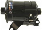 Part Number for Fuel filter
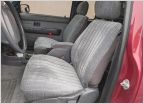 Can’t find seat covers!
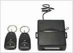 96taco power door locks
 What's the going rate for Line-X these days?
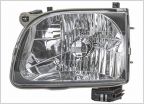 Best after market headlights (‘04)
CS144, Big 3, Big Battery Done. One Question
Discussion in '1st Gen. Tacomas (1995-2004)' started by TheDonkey, Jan 12, 2014.


