

-
Welcome to Tacoma World!
You are currently viewing as a guest! To get full-access, you need to register for a FREE account.
As a registered member, you’ll be able to:- Participate in all Tacoma discussion topics
- Communicate privately with other Tacoma owners from around the world
- Post your own photos in our Members Gallery
- Access all special features of the site
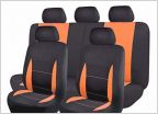 Seat Covers
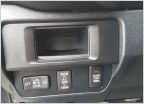 Rocker Switch Plate
 Where do these parts go?
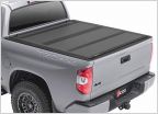 What's the Best Deal for a Bakflip MX4 Cover? (448426)
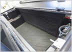 Fold-a-Cover Personal Caddy for 3rd gens - Thoughts?
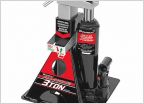 Powerbuilt All in one bottle jack and jack stand
Front ARB Air Locker DIY & Install Thread
Discussion in '3rd Gen. Tacomas (2016-2023)' started by ShimStack, Nov 3, 2020.
Page 1 of 2
Page 1 of 2


