

-
Welcome to Tacoma World!
You are currently viewing as a guest! To get full-access, you need to register for a FREE account.
As a registered member, you’ll be able to:- Participate in all Tacoma discussion topics
- Communicate privately with other Tacoma owners from around the world
- Post your own photos in our Members Gallery
- Access all special features of the site
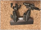 Tech Deck with Ram Accessories - SOLD
 FS: 2nd Gen mid travel suspension and more – Southern California
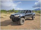 2011 DCSB Mega Sale!!!!
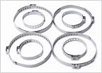 Tie Rod Boot Clamps
FS 1 piece driveshaft (feeler)
Discussion in '2nd Gen Tacoma Parts Marketplace (2005-2015)' started by Sgtfluffy16, Jan 11, 2012.
Page 2 of 2
Page 2 of 2


