1. Welcome to Tacoma World!

    You are currently viewing as a guest! To get full-access, you need to register for a FREE account.

    As a registered member, you’ll be able to:
    • Participate in all Tacoma discussion topics
    • Communicate privately with other Tacoma owners from around the world
    • Post your own photos in our Members Gallery
    • Access all special features of the site

How To: Automatic/Power Tailgate lock

Discussion in '1st Gen. Tacomas (1995-2004)' started by moto.mike, Oct 26, 2020.

  1. Oct 26, 2020 at 9:31 PM
    #1
    moto.mike

    moto.mike [OP] Well-Known Member

    Joined:
    Oct 13, 2020
    Member:
    #343706
    Messages:
    1,476
    First Name:
    take a guess...
    Oakland
    Vehicle:
    2004 Xtra Cab 4x4 TRD SR5
    Hey everyone,
    This has generated some interest, so I figured I'd make a thread.

    I used this thread for ideas on the automatic/powered lock: https://www.tacomaworld.com/threads/10-diy-power-lock-tailgate.424052/
    and this thread for the manual pop & lock solution: https://www.tacomaworld.com/threads/1st-gen-pop-lock-tailgate-lock-install.226392/

    The pop & lock is basically an interference device that prevents the handle from being pulled. 50 bucks is way too much for that. The automatic one is $100. No thanks.

    So I went ahead and bought:
    lock actuators
    16 ga wire
    wire auto conduit
    splicers
    quick disconnects (for the connection between the actuator and the wires that lead to the passenger side door)
    and easy peasey wire connectors
    you'll also need zip ties...but you have plenty of those already, right?

    There's 3 major steps:
    1) getting the actuator installed, arm cut to length, wires spliced to the disconnects.
    2) splicing into the wires at the passenger door
    3) running the wire from the passenger door splice back to the tail gate.

    I did it as steps 1, 3, and 2. It might make more sense to do it in the order listed above. Might be worthwhile to do steps 2 and 3 and then do a test connect to the actuator to make sure it works...I just went for it.

    First open up your tail gate - remove the screws holding the top panel on.
    Figure out where you want to put the actuator. I put it on the passenger side of the handle since that's where the 'lever' is that engages the arms/rods for the tail gate latches. I also put it on that side since I was planning on running the wires to the passenger side. This way the tail gate lock is linked to the passenger door locks, so it unlocks the second time you push the unlock button on your key fob.

    Remove the tail gate latch arms/rods (see other thread, but basically flip open the little clips and remove the arms). Then unscrew the handle and remove it. This will let you remove the handle so you can drill the hole for where the actuator rod will go.

    I drilled a small pilot hole first since I wasn't sure if this would work the way I was planning.
    In any event, drill a hole through the handle as high as you can in that little slot. Be careful as it's plastic...
    (in the pictures it's on the opposite side of the handle where i put it.)
    [​IMG]


    Final hole size is 7/64" I think (the size of the actuator rod). The rod should slide in easily. When its pushed through the hole it interferes with the handle and you can't pull it open.

    [​IMG]

    The actuator comes with everything you need...however, I used self tapping screws so that I wouldn't poach the other screws for the other actuator if you wanted to use it down the road for something else.
    The actuator rod passes through a hole in the rib in the tail gate and doesn't interfere with the tail gate latch arm. I tried to keep the throw on this fairly straight, but you can always bend the actuator arm if you needed to.
    Cut down the arm to the right length where it retracts fully from the pull handle. I've got it trimmed so it sits in the drill hole when it's not engaged; this also serves as a guide for it so it stays in the right position to engage.
    One thing to note, there's a slight bulge in the removable tail gate panel once you button this up based on where I put the screws...get flatter screws or adjust location as you see fit.

    I spliced the wires from the actuator to a piece of the 16 gauge wires I bought. I used those fancy solder/heat shrink linked above, but you can easily do it the more traditional way. I don't have a picture of this.

    I then connected the spliced wires coming from the actuator to a quick disconnect.
    The ones in the link above are kind of a pain in the a, so choose your preferred brand/style.
    I tucked the quick disconnect underneath the hinge plate and secured with a zip tie.
    The reason for this is if you are planning on (or are forced to) taking your tailgate off.


    I ran the wires through the tail light housing area and out the bottom...another option would be to run it down through the hole where you put the rod to lower the spare tire.

    Here is where the wires come out of the tail light housing. View is looking up from underneath the truck at the corner of the bed, under the bumper. The dusty conduit is from the tail light, the fresh conduit is the tail gate lock wires.
    [​IMG]

    From here, I ran the wires in the conduit along the chassis, trying to keep them away from pinch points and the exhaust. Your routing may vary.
    [​IMG]
    dusty conduit in foreground is from the tail light, tail gate lock conduit runs down the frame, zip tie as you go...

    ...over the top of the rear shock (it's the bright reflection in the left hand side of the photo)...
    [​IMG]

    ...around this bushing..not sure if this actually moves..but better safe than sorry...
    (here you can see a couple of grommets where you could run it into the cab, but i didn't want to mess with it)....
    [​IMG]

    ....back along the frame and up through where the O2 sensor wires come into the cab...
    [​IMG]


    I ended up running the wires into the cab where the O2 sensor comes in under the passenger seat since it's already set up. There is another location at the back of the cab, but it was getting late and this was super easy.
    [​IMG]


    Run the wires in the channel under the foot board and up to where the kick panel is.
    [​IMG]
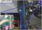
    Here you will see the wiring coming in from the passenger door. You want to splice into the Blue wire and the Blue/White wire. It's the lower of the two connectors (not the 5 wire one). I managed to get the polarity right on my first try, but if you get it reversed, then the actuator will retract when you want it to extend.

    [​IMG]

    My wiring was:
    - blue wire from actuator to black wire to blue/white wire on the passenger door.
    - green wire to red wire to blue wire on the passenger door.

    This is slightly different on double cab models, per pop and lock:
    2 door models - remove the kick panel and locate the wiring harness leading to the driver’s door. Locate the BLUE wire and the BLUE/WHITE striped wire. Attach the two blue wire taps to them and squeeze them shut with a pair of pliers.
    4 door models - wire colors remain the same, however connection must be made in the driver’s side rear door step plate and ‘B’ pillar.
    https://vehiclesecurityinnovators.com/wp-content/uploads/2019/06/PL8510-toyota-tacoma.pdf


    So now if you hit the lock button on your fob, it will lock your doors and the tail gate lock. When you press unlock on your fob once, it'll unlock the driver side door.
    When you press it again, it unlocks the driver side door and tail gate.
    If you had wired it to the driver side, it would unlock with the first press.

    Button everything up and tell all your friends how awesome you are.
     
    billpete, Plkyone and SwampYota like this.
  2. Oct 27, 2020 at 6:02 AM
    #2
    SwampYota

    SwampYota Strange things are afoot at the Circle K

    Joined:
    Apr 11, 2016
    Member:
    #184044
    Messages:
    4,306
    Gender:
    Male
    First Name:
    Jon
    Concord, North Carolina
    Vehicle:
    '03 Tacoma SR5 TRD 5VZ-FE, 5 Speed
    Floor mats
    Very cool @moto.mike thanks for the detailed write up.
     
  3. Oct 27, 2020 at 5:30 PM
    #3
    Plkyone

    Plkyone Well-Known Member

    Joined:
    Nov 3, 2018
    Member:
    #271563
    Messages:
    273
    This site contains affiliate links for which the site may be compensated.
    #3
    moto.mike[OP] likes this.
  4. Oct 27, 2020 at 6:59 PM
    #4
    moto.mike

    moto.mike [OP] Well-Known Member

    Joined:
    Oct 13, 2020
    Member:
    #343706
    Messages:
    1,476
    First Name:
    take a guess...
    Oakland
    Vehicle:
    2004 Xtra Cab 4x4 TRD SR5
    nice...that's basically a rip off of the pop and lock one...not bad for 33 bucks...had i known i might've just bought that...
     
    Plkyone likes this.
  5. Apr 23, 2023 at 8:17 PM
    #5
    1stGenTacoChef

    1stGenTacoChef New Member

    Joined:
    Apr 23, 2023
    Member:
    #423067
    Messages:
    1
    Gender:
    Male
    Used something similar, but needed to switch wiring per OP. Blue wire to blue. Green wire to blue/white.
     
    This site contains affiliate links for which the site may be compensated.
    #5
To Top