

-
Welcome to Tacoma World!
You are currently viewing as a guest! To get full-access, you need to register for a FREE account.
As a registered member, you’ll be able to:- Participate in all Tacoma discussion topics
- Communicate privately with other Tacoma owners from around the world
- Post your own photos in our Members Gallery
- Access all special features of the site
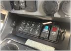 ARB CKMA12 Simple Wiring
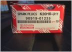 How To: Spark Plug Change (1 GR-FE)
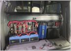 Storage Solutions Behind Rear Seat
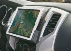 IPad for back up camera?
 Warn winch remote extension
 Green Earth Technologies "Green Oil"
Off-Grid Engineering Dual Battery System Q&A
Discussion in 'Technical Chat' started by HeliMedic, Jan 5, 2017.
Page 6 of 39
Page 6 of 39
Products Discussed in


