

-
Welcome to Tacoma World!
You are currently viewing as a guest! To get full-access, you need to register for a FREE account.
As a registered member, you’ll be able to:- Participate in all Tacoma discussion topics
- Communicate privately with other Tacoma owners from around the world
- Post your own photos in our Members Gallery
- Access all special features of the site
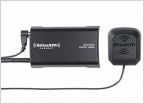 SiriusXM Tuner/adapter - built into head unit?
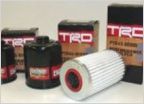 17 TRD 4x4 OFF Road Oil Filter which one?
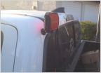 Any way to get the Bluetooth on 2017 stock radio to transmit
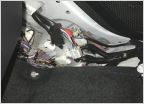 Pop n lock on a 3rd gen with JBL
 60k Transmission drain/fill
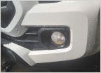 Anyone else's foglight have swamp ass?
Switch wiring with 5-terminal switches
Discussion in '3rd Gen. Tacomas (2016-2023)' started by Taurus22, Jul 30, 2018.


