-
Welcome to Tacoma World!
You are currently viewing as a guest! To get full-access, you need to register for a FREE account.
As a registered member, you’ll be able to:- Participate in all Tacoma discussion topics
- Communicate privately with other Tacoma owners from around the world
- Post your own photos in our Members Gallery
- Access all special features of the site
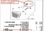 Seeking part number for gen1 turn signal harness
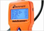 OBDII Scanner from Autozone. Good value?
 Drive line Backlash is killing me
 1st gen 1997 tacoma lug nuts
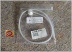 As of this date, does Toyota have a good rust proofing system for their vehicles?
Yet another heated seat post! (With a twist?)
Discussion in '1st Gen. Tacomas (1995-2004)' started by crazylike, Feb 12, 2021.
Page 1 of 2
Page 1 of 2