-
Welcome to Tacoma World!
You are currently viewing as a guest! To get full-access, you need to register for a FREE account.
As a registered member, you’ll be able to:- Participate in all Tacoma discussion topics
- Communicate privately with other Tacoma owners from around the world
- Post your own photos in our Members Gallery
- Access all special features of the site
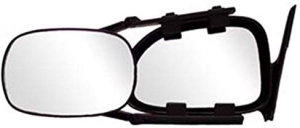
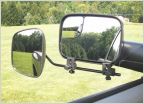 Please Help with finding quick detach mirrors for towing
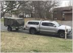 M101a2 Overland Trailer Build
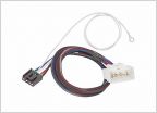 2019 Brake Controller Hookup
 Hello everyone, in a little bit of a panic...
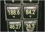 How to lower your trans temps
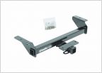 Draw-Tite 75238 Hitch for 3rd Gens - $41 on Amazon
The Tacoma Towing Bible
Discussion in 'Towing' started by maverick491, Nov 18, 2007.
Page 1 of 100
Page 1 of 100