-
Welcome to Tacoma World!
You are currently viewing as a guest! To get full-access, you need to register for a FREE account.
As a registered member, you’ll be able to:- Participate in all Tacoma discussion topics
- Communicate privately with other Tacoma owners from around the world
- Post your own photos in our Members Gallery
- Access all special features of the site
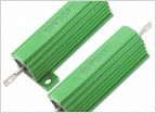 LED flasher for 08' with DRL
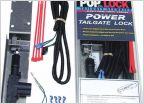 Cap and tailgate lock question...
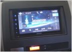 What after market head unit you running???
 Any cool aftermarket gadgets to replace the temperature/compass display?
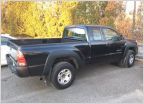 New 2nd gen owner ('07)
Illuminated Ignition Ring Mod
Discussion in '2nd Gen. Tacomas (2005-2015)' started by JdevTac, Feb 9, 2015.
Page 1 of 20
Page 1 of 20