

-
Welcome to Tacoma World!
You are currently viewing as a guest! To get full-access, you need to register for a FREE account.
As a registered member, you’ll be able to:- Participate in all Tacoma discussion topics
- Communicate privately with other Tacoma owners from around the world
- Post your own photos in our Members Gallery
- Access all special features of the site
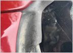 ID A Missing Part
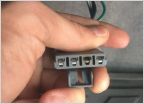 Blower Motor Resistor Connector
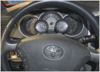 Oil pressure/temp gauge install
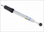 5100’s to Help Ride Quality
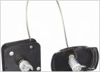 Lowering spare tire using factory tool
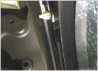 Leaky Roof? 3rd brake light?
Ram Mount Feeler
Discussion in '2nd Gen. Tacomas (2005-2015)' started by Lostsheep, Feb 21, 2017.
Page 1 of 56
Page 1 of 56
Products Discussed in


