

-
Welcome to Tacoma World!
You are currently viewing as a guest! To get full-access, you need to register for a FREE account.
As a registered member, you’ll be able to:- Participate in all Tacoma discussion topics
- Communicate privately with other Tacoma owners from around the world
- Post your own photos in our Members Gallery
- Access all special features of the site
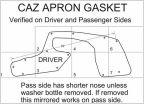 PDF template for splash guard / fender liner thingies
 Code reader
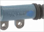 Leaking clutch master cylinder
 Where to get a new SecuriKey??
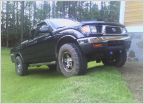 Parent's Tacoma. More aggressive tires
 Electric Fan conversion question...
How To: Automatic/Power Tailgate lock
Discussion in '1st Gen. Tacomas (1995-2004)' started by moto.mike, Oct 26, 2020.
Products Discussed in


