

-
Welcome to Tacoma World!
You are currently viewing as a guest! To get full-access, you need to register for a FREE account.
As a registered member, you’ll be able to:- Participate in all Tacoma discussion topics
- Communicate privately with other Tacoma owners from around the world
- Post your own photos in our Members Gallery
- Access all special features of the site
Quick Links: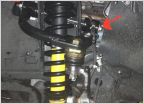 OME kit finally installed!!
  Desertjunkie760's 2011 Not So Basic but Never a Bad Bitch Build Thread
  Brians F/R Locked Long Travel Camping and Overland Build
  My long overdue build thread!!
  Will.i.was Prerunner/4x4 twin stick converted, supercharged fbo long travel build
  SC2SC Tacoma Journal and Experience
2012 Molon Labe Build-up
Discussion in '2nd Gen. Builds (2005-2015)' started by Molon Labe, Oct 16, 2012.
Page 1 of 5
Page 1 of 5
Products Discussed in


