-
Welcome to Tacoma World!
You are currently viewing as a guest! To get full-access, you need to register for a FREE account.
As a registered member, you’ll be able to:- Participate in all Tacoma discussion topics
- Communicate privately with other Tacoma owners from around the world
- Post your own photos in our Members Gallery
- Access all special features of the site
 All-Pro Leaf Springs
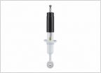 2nd gen Rear shock options WITH lengths
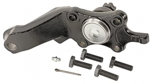
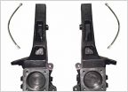 QSA 4" Lift Spindles
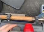 Universal Bump stops
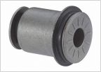 Need help with a control arm bushing part number
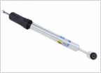 2.5 lift
Bilstein 5100 OME 884 Headstrong Progressive AAL Installation Write-Up
Discussion in 'Suspension' started by aahowk423, Jun 17, 2019.